


uPAC-5207
Wireless ISaGRAF based uPAC with MicroSD Expansion, 512KB Battery Backup SRAM, 80 Mhz CPU, Communicates Over RS-232 and RS-485, 2G GPRS, Supports operating temperatures from -25 ~ +75°C and has a MiniOS7 Operating System. uPAC-5207 is phased out and replaced by uPAC-7186EG and uPAC-7186EGD.

Features
The uPAC-5207 has officially been phased out and will no longer be available. It has now been replaced by uPAC-7186EG and uPAC-7186EGD.
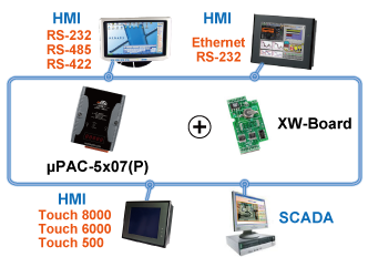
The μPAC-5x07(P) series is a palm-size programmable automation controller. It has a 80186 CPU, SRAM, Flash, Ethernet port, RS-232 and RS-485 port. With a DOS-like OS (MiniOS7) and a developed firmware running inside, it can act like a small PC.
For hardware expansion, it also supports an I/O expansion bus. The I/O expansion bus can be used to implement various I/O functions such as DI, DO,A/D, D/A, Timer/Counter, UART, and other I/O functions. Nearly all kinds of I/O functions can be implemented by this bus. The bus can support one board. There are more than 10 boards available for μPAC-5x07(P) series, you can choose one of them to expand hardware features.
μPAC-5x07(P) is the model of μPAC-5x07 with PoE (Power-over-Ethernet). PoE allows power and data to be carried over a single Ethernet cable, so a device can operate solely from the power it receives through the data cable. This innovation allows greater flexibility in office design, higher efficiency in systems design, and faster turnaround time in systems design, and faster turnaround time in set-up and implementation.
Hot Features
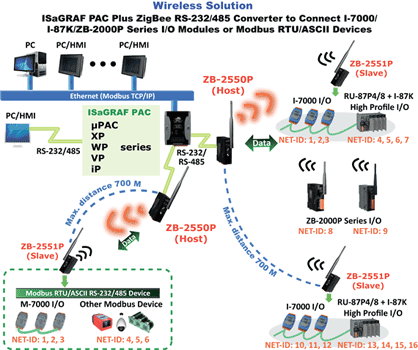
ZigBee Wireless Solution |
| ISaGRAF PAC plus ZB-2550P and ZB-2551P (ZigBee to RS-232/485 Converters) can apply wireless communication, reduce the wiring cost, and achieve remote I/O control and data acquisition. |
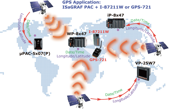
GPS Applications: ISaGRAF PAC plus I-87211W or GPS-721 |
| uPAC-5007(P)/5207 can support one I-87211W via COM1 (RS-232) or I-87211W/GPS-721 as RS-485 remote GPS I/O. |
| For doing auto-time-synchronization and getting local Longitude and Latitude. |
| Note: uPAC-5107(P), uPAC-5307 has built-in GPS function. |
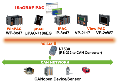
Integrate with CAN/CANopen Devices and Sensors |
| uPAC-5x07(P) Supports max. 3 I-7530 (RS-232 to CAN) Converters. |
Send Email with One Attached File |
| uPAC-5x07(P) can send Email with one attached file via Ethernet Port. The maximum file size is about 488K bytes. |
| One Email can send to 10 receivers at one sending. |
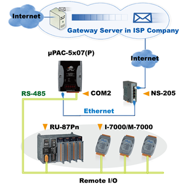
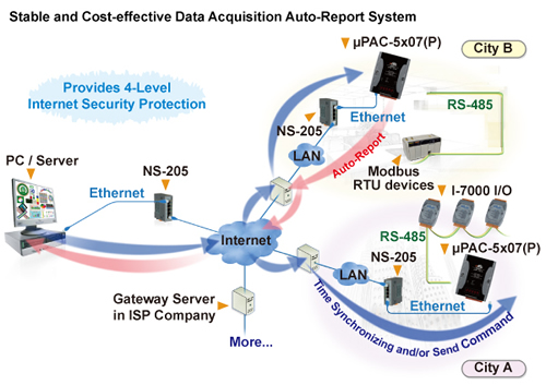
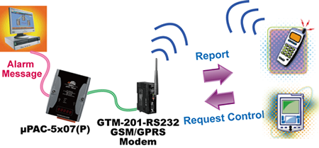
Data Acquisition Auto-Report System |
VC++ 6.0, VB 6.0 and ISaGRAF demo programs are available. ISaGRAF PACs can use UDP/IP Client to auto-report acquisition data & control data to local or to remote internet PC/Server. Advantage: Each ISaGRAF PAC in the different location doesn't require a fixed Internet IP. |
 |
Communication Interface |
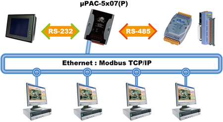
The uPAC-5x07(P) provides Ethernet solutions. It contains 3 communication ports, COM1: RS-232, COM2: RS-485, Ethernet port: 10/100 Mbps Ethernet. These different communication ports can provide various kinds of usage include RS-485 networking, controller to controller data-exchange, Modbus RTU/ASCII Master Protocol, Modbus RTU/TCP Slave Protocol, Remote I/O extension, linking with HMI/MMI, program download/upload, and debugging.
|

Modbus RTU/TCP Slave Ports |
Modbus RTU (RS-232/485/422): max. 2 Modbus RTU Slave ports Modbus TCP/IP: max. 6 Modbus TCP Slave connections |
Modbus RTU/ASCII Master Ports |
| Modbus RTU/ASCII (RS-232/485/422): max. 2 Modbus RTU/ASCII Master ports. |
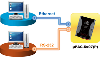
Multi-Client Connection |
|
Each uPAC-5x07(P) has an IP address and with a fixed port No. of 502. With Modbus TCP/IP protocol, up to 6 PCs can link to one uPAC-5x07(P) through Ethernet. With Modbus serial protocol, another PC or MMI can link to the COM1 (RS-232) port of the μPAC-5x07(P). Therefore, the maximum number of clients that can be linked is 7. |
Expansion Boards and Remote I/O Modules
RU-87Pn Features
Hot Swap Auto-Configuration - Configurations of I-87K I/O modules can be pre-configured and stored in the nonvolatile memory of the RU-87Pn. Easy Duplicate System- Using the DCON Utility, you can easily make a backup of the I-87K module configurations and write to another RU-87Pn. Full Software Support - The free-of-charge software utility and development kits are included. |
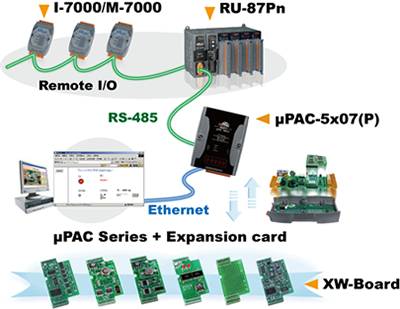
I/O Expansion Boards |
The uPAC-5x07(P) has an I/O expansion bus which can plug One I/O expansion board. Linking the I-7000 & I-87K module for Remote I/O The uPAC-5x07(P) PAC can use its COM2 (RS-485) port to link to ICP DAS's "I-7000" & "I-87K" series of Remote I/O modules. This configuration can be very useful in applications that require distributed Remote I/O throughout the system.
|

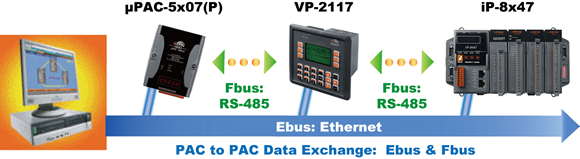
Data Exchange: Fbus & Ebus
Fbus ( RS-485 Network ) Each uPAC-5x07(P) can use its RS-485 port (COM2) to talk to each other via the Fbus communication mechanism. Fbus can be used to broadcast data to each controller or each controller can request to send or receive data from any other controller on the same Fbus network. Ebus ( Ethernet Network) Each uPAC-5x07(P) can use its Ethernet port to talk to each other via the Ebus communication mechanism. When PC is talking with controllers via Ethernet, the controllers can also talk to each other via the same Ethernet; It makes the configuration more flexible and faster. |
Data Log
ICP DAS provides a freeware “UDLoader.exe” to load the data stored in battery-backup SRAM via RS-232 or Ethernet port.
PWM : Pulse Width Modulation Output |
All XW-Board series DO boards support PWM output. Up to 8-ch for one controller. 500 Hz max. for Off=1 ms & On=1 ms. Available output square wave: Off = 1 ~ 32767 ms, On = 1 ~ 32767 ms.
|
|
Specifications
| Models | Regular version | μPAC-5007 μPAC-5007P |
μPAC-5107 μPAC-5107P |
μPAC-5207 | μPAC-5307 |
| PoE version | |||||
| System Software | |||||
| OS | MiniOS7 | ||||
| Development Software | |||||
| ISaGRAF Version 3 | IEC61131-3 standard. Languages: LD, ST, FBD, SFC, IL & FC | ||||
| Max. Code Size | Accepts max. 64 KB ISaGRAF code size (Appli.x8m must < 64 KB) | ||||
| Power Supply | |||||
| Protection | Power reverse polarity protection | ||||
| Frame Ground | Yes (for ESD Protection) | ||||
| Redundant Power Inputs | Yes | ||||
| Input Range | +12 ~ +48 VDC | ||||
| Power over Ethernet | IEEE 802.3af, Class 1 (for PoE version) | - | |||
| Power Consumption | 2 W ; μPAC-5x07D/5x07PD: 2.5 W | ||||
| General Environment | |||||
| Temperature | Operating: -25 ~ +75 °C, Storage : -30 ~ +80 °C |
||||
| Humidity | 10 ~ 90 % RH (non-condensing ) | ||||
| System | |||||
| CPU | 80186 or compatible (16-bit and 80 MHz) | ||||
| Watchdog Timer | Yes, default 0.8 second | ||||
| RTC (Real Time Clock) | Provide second, minute, hour, date, day of week, month, year | ||||
| SRAM | 768 KB | ||||
| Battery Backup SRAM | 512 KB (Data valid up to 5 years, max. 1024 retain variables). | ||||
| FLASH | 512 KB (100,000 erase/write cycles). | ||||
| microSD Expansion | Yes (ISaGRAF doesn’t support). | ||||
| NVRAM | 31 bytes (Battery backup, data valid up to 10 years). | ||||
| EEPROM | 16 KB (Retention > 100 years; 1,000,000 erase/write cycles). | ||||
| 7-Seg. LED Display | 5-Digit 7-Seg. LED on the front of μPAC-5x07(D)/5x07P(D). It can display message and value. | ||||
| NET ID | User-assigned by software, 1 ~ 255 | ||||
| Hardware Serial Number | Yes, 64-bit hardware unique serial number. | ||||
| Communication Interface | |||||
| COM1 | RS-232: TxD, RxD, RTS, CTS, GND, Non-Isolated. |
||||
| COM2 | RS-485: D2+, D2-, Non-Isolated, self-tuner ASIC inside. |
||||
| Ethernet | RJ-45 x 1, 10/100 Base-TX, Program downloads port. |
||||
| LED Indicator | |||||
| Programmable LED | 2 (for User-Defined) | ||||
| Hardware Expansion | |||||
| I/O Expansion Bus | Yes (for one XW-board). | ||||
| Dimensions | |||||
| W x H x D | 91 mm x 123 mm x 52 mm | ||||
| PWM Output | |||||
| Pulse Width Modulation Output | All XW-series DO boards support PWM output. Max. 8 channels for one controller. 500 Hz max. for Off = 1 & On = 1 ms Output square wave: Off: 1 ~ 32767 ms, On: 1 ~ 32767 ms |
||||
| Counters | |||||
| Parallel DI Counter | All XW-series DI boards support DI counter. Max. 8 channels for one controller. Counter value: 32-bit 500 Hz max. Min. ON & OFF width must > 1 ms |
||||
| Remote DI Counter | All remote I-7000 & I-87K DI modules support counters. 100 Hz max. value: 0 ~ 65535 | ||||
| Remote High Speed Counter | Optional I-87082: 100 kHz max. ,32-bit | ||||
| Protocols | |||||
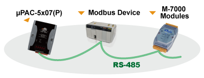
| Modbus RTU/ASCII Master Protocol | Up to 2 COM Ports (COM1, COM2 and COM3-in-XW-Board) support Modbus RTU/ASCII Master protocol to connect to other Modbus Slave I/O devices. Max. Mbus_xxx Function Block amount:128. | ||||
| Modbus RTU Slave Protocol |
Up to 2 COM Ports (COM1 and one of COM2/COM3-in-XW-Board) can support Modbus RTU Slave protocol for connecting ISaGRAF, PC/HMI/OPC Server & MMI panels. | ||||
| Modbus TCP/IP Protocol |
Ethernet port supports Modbus TCP/IP Slave protocol for connecting ISaGRAF & PC/HMI. Max. 6connections. | ||||
| Remote I/O | One of COM2 or (COM3: RS-485 in-XW-Board) supports I-7K, I-87K I/O modules as Remote I/O. I-87K series must plug on RU-87P (High profile) or I-87K (Low profile) I/O Unit. Max. 64 I/O modules for one PAC. |
||||
| Fbus | Built-in COM2 Port to exchange data between ICP DAS's ISaGRAF PACs. | ||||
| Ebus | To exchange data between ICP DAS's ISaGRAF Ethernet PACs via Ethernet port. | ||||
| Send Email | Actively or passively sending E-mail via Ethernet port through internet. Max.10 receivers for each sending and can send E-mail with an attached file. (Max. file size is about 488 KB) | ||||
| SMS: Short Message Service |
One of (COM1 or COM3: RS-232 in-XW-Board) can link to a GSM modem to support SMS. User can request data/control the controller by cellular phone. The controller can also send data & alarms to user's cellular phone. Optional GSM modem: GTM-201-RS232 (GSM/GPRS 850/900/1800/1900) Note: μPAC-5207, 5307 has built-in GPRS, no external GSM/GPRS modem required. |
||||
| User-defined Protocol | User can write his own protocol applied at COM1, COM2 & (COM3 ~ COM8 -in-XW-Board) by serial communication function blocks. | ||||
| MMICON/LCD | One of (COM3: RS-232 in-XW-Board) supports ICP DAS's MMICON. The MMICON is featured with a 240 x 64 dot LCD and a 4 x 4 Keyboard. User can use it to display picture, string, integer, float, and input a character, string, integer and float. | ||||
| Redundancy Solution | Two PACs plug with XW107 in slot0. One is Master, one is Slave. Master handles all inputs & outputs at run time. If Master is damaged (or power off), Slave will take over the control of Bus7000b. If Master is alive from damaged (or power up again), it takes the control of Bus7000b again. The change over time is about 5 seconds. Control data is exchanging via Ebus (if using a cross cable, no require any Ethernet Switch). All I/O should be RS-485 I/O except the status I/O in the slot 0: XW107. | ||||
| CAN/CANopen | Use COM1 or COM3 ~ COM8 (at the XW5xx RS-232 X-board) to connect one I-7530: the RS-232 to CAN converter to support CAN/CANopen devices and sensors. One PAC supports max. 3 RS-232 ports to connect max. 3 I-7530 modules. | ||||
References and Support
Customer Reviews (0)
Be the first to leave a review.


M-7019R
8-channel Universal ...
$0.00 Each
Quantity added:


