CAN-8x23
CANopen Embedded Device with 1 or 2 I/O Expansions. Formerly I-8KCPS1/2.
Features
CANopen is a communication protocol, based on the intelligent field bus(CAN bus). It was developed as a standardized embedded network with highly flexible configuration capabilities. It provides standardized communication objects for real-time data (Process Data Objects, PDO), configuration data (Service Data Objects, SDO), network management data (NMT message, and Error Control), and special functions (Time Stamp, Sync message, and Emergency message). CANopen is used in many application fields, such as medical equipment, off-road vehicles, maritime electronics, public transportation, and building automation.
I-8KCPS1/2 main control units are specifically designed as the slave device of CANopen protocol. It follows the CANopen Spec DS-301 V4.01 and DSP-401 V2.1, and provides many features for users, such as: dynamic PDO, EMCY object, error output value, SYNC cyclic and acyclic. In order to
expand I/O channel flexibility, an I-8KCPS1/2 supports 1/2 slot(s) for I/O expansion and suits with a lot of ICPDAS DI/AI/DO/AO slot modules. Users can choose DI/DO/AI/AO modules of I-87K series or I-8000 series to fit the customized practice applications. In addition, we also provide utility tool to allow users to create the EDS file dynamically. The EDS file is based on CANopen SP306 and can be compatible with different CANopen master interfaces. The application architecture is as image on the right. |
||
|
||
I-8KCPSx Utility
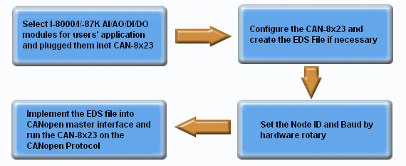
I-8KCPS1/2 can automatically scan the I-8K/I-87K modules plugged in the main unit and assign these modules to specified applications. Before users apply the 8KCPS1/2 in CANopen data acquisition applications, they must understand the relationship between the CANopen application and the device object dictionary in I-8KCPS1/2. We provide the I-8KCPS1/2 Utility Tool (CAN slave utility, CAN_SL.exe) to allow users to view important information, such as slot module information, Rx and Tx PDO mapping, and the device object dictionary. After finishing the utility configuration, the EDS file will be created for the I-8KCPS1/2 device. If the I-8KCPS1/2 EDS file is not needed for the application, users only need to set the Node ID and baud by the hardware rotary switch. After wire connection and turning on the I-8KCPS1/2, it can work on the CAN bus network through CANopen protocol . I-8KCPSx Design Flowchart
Applications
 |
||
Specifications
Model |
I-8KCPS1 |
I-8KCPS2 |
| CPU | 80186, 80MHz |
|
| Flash | 512K bytes |
|
| SRAM | 512K bytes |
|
| EERROM | 2K bytes (Can upto 128K bytes or change to 2K/8K FRAM) |
|
| NVRAM | 32 bytes |
|
| Real Time Clock | 16 bit |
|
| Watch Dog Timer | CPU Built-in |
|
| LEDs | PWR led , RUN led , ERR led |
|
| CAN Port | 5-pin screw terminal connector |
|
| CAN Controller | Phillip SJA1000T
|
|
| CAN Transceiver | Phillip 82C250/251 |
|
| CAN 2.0A/2.0B Supported | ˇ |
|
| Isolated | 2500Vrms on CAN side |
|
| Terminal Resister | 120 ohm terminal resister selected by jumper |
|
| Transfer Rate | 125K, 250K, 500K |
|
| I/O Expasion Slot | 1 slots |
2 slots |
| Power Supply | 20W unregulated +10VDC to +30Vdc |
|
| Operating Temp | -25C to 75C |
|
| Storage Temp | -30C to 85C |
|
| Humidity | 5 ~ 95% |
|
| Dimensions | 63x110x75.5 mm |
115x110x75.5 mm |
IO Type |
Module Name |
DI |
I-8040/ I-8051/ I-8052/ I-8053/ I-8058/ I-87040/ I-87051/ I-87052/ I-87053/ I-87058/ |
DO |
I-8037/ I-8041/ I-8056/ I-8057/ I-8060/ I-8064/ I-8065/ I-8066/ I-8068/ I-8069/ I-87041/ I-87056/ I-87057/ I-87060/ I-87064/ I-87065/ I-87066/ I-87068/ I-87069 |
DIO |
I-8042/ I-8054/ I-8055/ I-8063/ I-87042/ I-87054/ I-87055 I-87063/ |
AI |
I-87013/ I-87016/ I-87017/ I-87018/ |
AO |
I-8024 I-87022/ I-87024/ I-87026 |


