


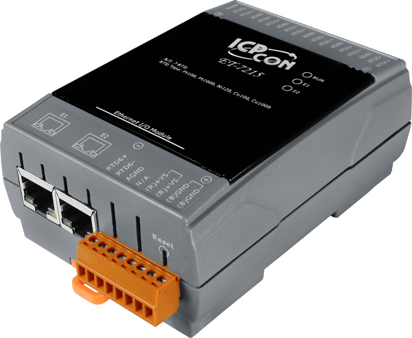
ET-7215
Modbus TCP Based Ethernet I/O Module with 2 Ethernet ports for daisy-chain networking and 7-channel RTD Inputs. Sensor types are Pt100, Pt1000, Ni120, Cu100, Cu1000. Communicable over Modbus TCP and Modbus UDP protocol, Supports operating temperatures of -25°C ~ +75°C (-13°F ~ 167°F) and has a din rail mount.

Features
The ET-7215 is specifically designed for long-distance RTD measurement. It features automatic compensation for three-wire RTD regardless of the length of wires and provides open wire detection for RTD measurement. The ET-7215 offers 7 channels, each of which could be connected with different kinds of RTD (Pt100, Pt1000, Ni120, Cu100, Cu1000). Also, The ET-7215 is fully RoHS-compliant and has qualification for 4 kV ESD protection as well as 2500 VDC intra-module isolation.
- Built-in Web Server
- Web HMI
- Support for both Modbus TCP and Modbus UDP Protocols
- Communication Security
- 2-port Ethernet Switch for Daisy-Chain Topology
- Dual Watchdog
- Wide Operating Temperature Range: -25 ~ +75°C
- I/O Pair Connection
- Built-in I/O
- RTD Input: 7 Channels
Applications
Building Automation, Factory Automation, Machine Automation, Remote Maintenance, Remote Diagnosis, Testing Equipment.
Daisy-Chain Ethernet Cabling
The ET-7200/PET-7200 Series has a built-in two-port Ethernet switch to implement daisy-chain topology. The cabling is much easier and total costs of cable and switch are significantly reduced.

LAN Bypass
LAN Bypass feature guarantees the Ethernet communication. It will automatically active to continue the network traffic when the ET-7200/PET-7200 looses its power.
Communication Security
Account and password are needed when logging into the web server. An IP address filter is also included, which can be used to allow or deny connections with specific IP addresses.
Support for both Modbus TCP and Modbus UDP Protocols
The Modbus TCP, Modbus UDP slave function on the Ethernet port can be used to provide data to remote SCADA software.
Built-in I/O
Various I/O components are mixed with multiple channels in a single I/O module, which provides the most cost effective I/O usage and enhances performance of the I/O operations.
Dual Watchdog
The Dual Watchdog is consists of a Module Watchdog and a Communication Watchdog. The action of AO,DO are also associated to the Dual Watchdog.
Module Watchdog is a built-in hardware circuit to monitor the operation of the module and will reset the CPU if a failure occurs in the hardware or the software. Then the Power-on Value of AO,DO will be loaded.
Communication Watchdog is a software function to monitor the communication between the host and the I/O module. The timeout of the communication Watchdog is proprgrammable, when the I/O doesn't receive commands from the host for a while, the watchdog forces the AO,DO to pre-programmed Safe Value to prevent unpredicatable damage of the connected devices.
Highly Reliable Under Harsh Environment
|
I/O Pair ConnectionThis function is used to create a AI/DI to AO/DO pair through the Ethernet. Once the configuration is completed, the I/O module can poll the status of remote AI/DI devices and then use the Modbus TCP protocol to continuously write to a local AO/DO channels in the background. |
 |
 |
Power-on Value and Safe Value
Besides setting by the set AO,DO commands, the AO,DO can be set under two other conditions.
Power-on Value: The Power-on Value is loaded into the AO,DO under 3 conditions: Power-on, reset by Module Watchdog, reset by reset command.
Safe Value: When the Communication Watchdog is enabled and a Communication Watchdog timeout occurs, the “safe value” is loaded into the AO,DO.
Specifications
| Software | |
| Built-In Web Server | Yes |
| Web HMI | Yes |
| I/O Pair Connection | Yes |
| Communication | |
| Ethernet Port | 2 x RJ-45, 10/100 Base-TX, Swtich Ports |
| PoE | - |
| Protocol | Modbus TCP, Modbus UDP |
| Security | ID, Password and IP Filter |
| Dual Watchdog | Yes, Module (0.8 seconds), Communication (Programmable) |
| LED Indicators | |
| for System Running | Yes |
| for Ethernet Link/Act | Yes |
| for DI/DO status | - |
| for PoE Power | - |
| 2 Way Isolation | |
| Ethernet | 1500 VDC |
| I/O | 3000 VDC |
| EMS Protection | |
| ESD (IEC 61000-4-2) | ±4 kV Contact for Each Terminal and ±8 kV Air for Random Point |
| EFT (IEC 61000-4-4) | ±2 kV for Power Line |
| Surge (IEC 61000-4-5) | ±2 kV for Power Line |
| Power | |
| Reverse Polarity Protection | Yes |
| Powered from Terminal Block | 12 ~ 48 VDC |
| Powered from PoE | - |
| Consumption | 3.6 W |
| Mechanical | |
| Dimensions (W x L x H) | 76 mm x 120 mm x 38 mm |
| Installation | DIN-Rail or Wall mounting |
| Environmental | |
| Operating Temperature | -25 ~ +75 °C |
| Storage Temperature | -30~ +80 °C |
| Humidity | 10 ~ 90% RH, non-condensing |
I/O Specifications
| RTD Input | |
| Channels | 7 (Differential) |
| Sensor Type | Pt100, Pt1000, Ni120, Cu100, Cu1000 |
| Wire Connections | 2/3 wire |
| Individual Channel Configuration | Yes |
| Resolution | 16-bit |
| Sampling Rate | 12 Samples/Second (Total) |
| Accuracy | +/-0.05% |
| Zero Drift | +/-0.5 μV/°C |
| Span Drift | +/-20 μV/°C |
| Overvoltage Protection | 110 VDC/VAC |
| Common Mode Rejection | 150 dB |
| Normal Mode Rejection | 100 dB |
| Input Impedance | >1M Ω |
| Overvoltage Protection | 120 VDC |
| Resistance Measurement | 3.2 KΩ Max. |
References and Support
Customer Reviews (0)
Be the first to leave a review.


ET-7002
Modbus TCP Based Rem...
$519.00 Each
Quantity added:


