


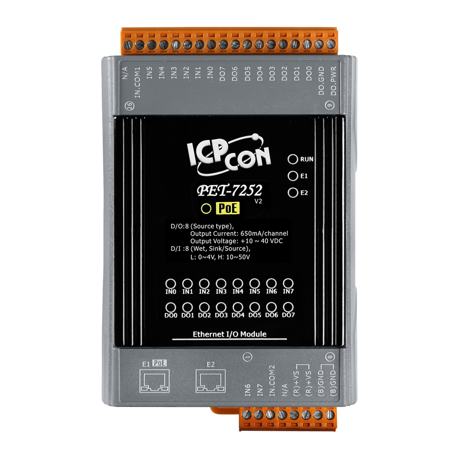
PET-7252
PoE Ethernet I/O Module with 2-port Ethernet Switch, with 8-ch Digital Input (32-bit Counter), 8-ch Digital Output. Support for both Modbus TCP and Modbus UDP Protocols. Built-in Web Server. Has operating temperatures of -25°C ~ +75°C (-13°F ~ +167°F)

Features

The PET-7252 provides 8 wet contact digital input channels and 8 source-type digital output channels. It features optical isolation for 2500 VDC of transient overvoltage protection but doesn’t provide channel-to-channel isolation. Each input channel can be used as a 32-bit counter and each output channel can drive 650 mA load. The power-on value and safe value of digital output channel are programmable. It can safely be used in applications where hazardous voltages are present.
- Built-in Web Server
- Web HMI
- Support for both Modbus TCP and Modbus UDP Protocols
- Communication Security
- 2-port Ethernet Switch for Daisy-Chain Topology
- Dual Watchdog
- Wide Operating Temperature Range: -25 ~ +75°C
- I/O Pair Connection
- Built-in I/O
- DI/Counter: 8 Channels
- DO: 8 Channels
Applications
Building Automation, Factory Automation, Machine Automation, Remote Maintenance, Remote Diagnosis, Testing Equipment.
Daisy-Chain Ethernet Cabling
The ET-7200/PET-7200 Series has a built-in two-port Ethernet switch to implement daisy-chain topology. The cabling is much easier and total costs of cable and switch are significantly reduced.

LAN Bypass
LAN Bypass feature guarantees the Ethernet communication. It will automatically active to continue the network traffic when the ET-7200/PET-7200 looses its power.
Communication Security
Account and password are needed when logging into the web server. An IP address filter is also included, which can be used to allow or deny connections with specific IP addresses.
Support for both Modbus TCP and Modbus UDP Protocols
The Modbus TCP, Modbus UDP slave function on the Ethernet port can be used to provide data to remote SCADA software.
Built-in I/O
Various I/O components are mixed with multiple channels in a single I/O module, which provides the most cost effective I/O usage and enhances performance of the I/O operations.
Dual Watchdog
The Dual Watchdog is consists of a Module Watchdog and a Communication Watchdog. The action of AO,DO are also associated to the Dual Watchdog.
Module Watchdog is a built-in hardware circuit to monitor the operation of the module and will reset the CPU if a failure occurs in the hardware or the software. Then the Power-on Value of AO,DO will be loaded.
Communication Watchdog is a software function to monitor the communication between the host and the I/O module. The timeout of the communication Watchdog is proprgrammable, when the I/O doesn't receive commands from the host for a while, the watchdog forces the AO,DO to pre-programmed Safe Value to prevent unpredicatable damage of the connected devices.
Highly Reliable Under Harsh Environment
|
I/O Pair ConnectionThis function is used to create a AI/DI to AO/DO pair through the Ethernet. Once the configuration is completed, the I/O module can poll the status of remote AI/DI devices and then use the Modbus TCP protocol to continuously write to a local AO/DO channels in the background. |
 |
 |
Power-on Value and Safe Value
Besides setting by the set AO,DO commands, the AO,DO can be set under two other conditions.
Power-on Value: The Power-on Value is loaded into the AO,DO under 3 conditions: Power-on, reset by Module Watchdog, reset by reset command.
Safe Value: When the Communication Watchdog is enabled and a Communication Watchdog timeout occurs, the “safe value” is loaded into the AO,DO.
Specifications
| Software | |
| Built-In Web Server | Yes |
| Web HMI | Yes |
| I/O Pair Connection | Yes |
| Communication | |
| Ethernet Port | 2 x RJ-45, 10/100 Base-TX, Swtich Ports |
| PoE | Yes |
| Protocol | Modbus/TCP, Modbus/UDP |
| Security | ID, Password and IP Filter |
| Dual Watchdog | Yes, Module (0.8 second), Communication (Programmable) |
| LED Indicators | |
| for System Running | Yes |
| for Ethernet Link/Act | Yes |
| for DI/DO status | Yes |
| for PoE Power | Yes |
| 2-Way Isolation | |
| Ethernet | |
| I/O | 2500 VDC |
| EMS Protection | |
| ESD (IEC 61000-4-2) | ±4 kV Contact for Each Terminal and ±8 kV Air for Random Point |
| EFT (IEC 61000-4-4) | ±2 kV for Power Line |
| Surge (IEC 61000-4-5) | ±2 kV for Power Line |
| Power Requirements | |
| Reverse Polarity Protection | Yes |
| Powered from Terminal Block | 12 ~ 48 VDC |
| Powered from PoE | Yes, IEEE 802.3af, Class1 |
| Consumption | 3.5 W |
| Mechanical | |
| Dimensions (W x L x H) | 76 mm x 120 mm x 38 mm |
| Installation | DIN-Rail or Wall mounting |
| Environmental | |
| Operating Temperature | -25°C ~ +75°C (-13°F ~ +167°F) |
| Storage Temperature | -30°C ~ +80°C (-22°F ~ +176°F) |
| Humidity | 10 ~ 90% RH, Non-condensing |
I/O Specifications
| Digital Input/Counter | ||
| Channels | 8 | |
| Contact | Wet Contact | |
| Sink/Source (NPN/PNP) | Sink/Source | |
| On Voltage Level | +10 VDC ~ +50 VDC | |
| Off Voltage Level | +4 VDC Max. | |
| Input Impedance | 10 kΩ | |
| Counters | Max. Count | 4,294,967,295 (32 bits) |
| Max. Input Frequency | 100 Hz | |
| Min. Pulse Width | 5 ms | |
| Overvoltage Protection | +70 VDC | |
| Digital Output | ||
| Channels | 8 | |
| Type | Isolated Open Collector | |
| Sink/Source (NPN/PNP) | Source | |
| Max. Load Current | 650 mA/channel at 25°C | |
| Load Voltage | +10 VDC ~ +40 VDC | |
| Overvoltage Protection | 47 VDC | |
| Overload Protection | - | |
| Short-circuit Protection | Yes | |
| Power-on Value | Yes, Programmable | |
| Safe Value | Yes, Programmable | |
References and Support
Customer Reviews (0)
Be the first to leave a review.


PET-7026
6-channel Data Acqui...
$389.00 Each
Quantity added:


